Introduction

Base inspection is the most important at all and also the first historically created for EBIs. In the start, it was applied to small inspectors used by glass bottles Producers. It is always present in the Empty Bottle Inspectors, as a minimum standard, jointly with a few others like the High Frequency Residual Liquid control and the Finish inspection.
Operating Principle
Its operative principle implies a quite long time-ordered sequence:
Processed image of the Bottle base ![]()
Horizontal and vertical automatic centering algorithm ![]()

The base of a glass bottle, as shown by an EBI, after the image processing. A device adopting Artificial Intelligence to separate glass characteristics of the bottle, like the knurling marks, by real foreign objects in the bottle![]()
- a bottle neck starts to obscure a thin-beam laser trigger photosensor;
- after a delay time, a flasher (strobo or LED matrix) illuminates the base bottom;
- the original illumination of the sources reach an interposed opaline light diffusor, to equalize the illumination;
![]() Into the Optoelectronics’ cabinet of an Empty Bottle Inspector. The illuminator of the bottle Base inspection is a light source set under the passing bottles’. It provide illumination to all different kinds of Base Inspections, Inner Sidewall Inspection and Infra Red (IR) Mineral Oil control by mean of a serie of cascaded Beam Splitters. Light diffused by an opaline filter, then a polariser filter. Then, the light enters the glass bases of the bottles. It’ll get out what has not been absorbed by the eventual defects. Out of the bottles’ finishes the camera optics receives this light by mean of a second polariser, accurately aligned with the first. Then the polarized light gets into the front lens of the Base Camera optics. Later diaphragmed and finally focused over the CMOS- or CCD-sensor. Signal later addressed to powerful electronics, capable to process over until 7 billions of analog values per second
Into the Optoelectronics’ cabinet of an Empty Bottle Inspector. The illuminator of the bottle Base inspection is a light source set under the passing bottles’. It provide illumination to all different kinds of Base Inspections, Inner Sidewall Inspection and Infra Red (IR) Mineral Oil control by mean of a serie of cascaded Beam Splitters. Light diffused by an opaline filter, then a polariser filter. Then, the light enters the glass bases of the bottles. It’ll get out what has not been absorbed by the eventual defects. Out of the bottles’ finishes the camera optics receives this light by mean of a second polariser, accurately aligned with the first. Then the polarized light gets into the front lens of the Base Camera optics. Later diaphragmed and finally focused over the CMOS- or CCD-sensor. Signal later addressed to powerful electronics, capable to process over until 7 billions of analog values per second
- the light getting out by the interposed opaline light diffusor, reach a polarizer filter, to let only photons whose spin angle fall in a preferential band of angles pass to the base bottom;
- the light getting out by the polarizer filter, finally reach the base bottom, interacting with the glass and eventual foreign objects in the base bottom being refracted, reflected and diffracted;
- portion of it continues its travel up, toward the neck of the bottle, now carrying the additional information about the base bottom;
- immediately before the optic system, is interposed a second polarizer filter, of the same type as the bottom. Its angle is finely oriented to allow maximum energy transfer for the photons’ spin precedently chosen by mean the bottom filter, cutting out the other photons, otherwise destructively interfering when “landing” in the same pixel. Filtering, allows a very important increase on the S/N (Signal-to-Noise) ratio of the image, in laymen words, its contrast. A difference not directly visible in a black and white image by (qualitative) human eyes, but results impressive as seen by the (quantitative) pixels of the CCD camera. Defects’ borders look much sharper where eyes see no difference at all;
- polarized gets out of the second polarizer and reaches the CCD or CMOS camera, in nearly all applications a black and white model with at least SVGA capability. Interestingly, results are quite independent on the total number of pixels of the camera and proportional to:
- optics' quality;
- optics' setup;
- adoption of polarizer filters;
- quality of the algorithms later processing the image signal originating by the camera
- the information conveyed to each one pixel in the CCD-surface has the X,Y coordinates expressed in the rectangular reference system of the CCD-sensor, where homologue parts of different bottles shall fluctuate on different positions due to several reasons (ellipsoidal bottles, sponge belt system not allowing a firm contact with bottles due to this prone to microinclinations during illumination and CCD-framing, etc.).
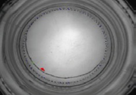
- the system is not yet ready to evaluate for the presence of defects. A second reference system exists in the Base inspection, showed by the figure on right side. By mean of scan segments (green colour), it is evaluated where lies the external border of each bottle, then inferred its centre. In the image at right side, the centroid of the base is evaluated as a blue coloured spot in the centre of the serie of blue colour radial segments. To these coordinates, are referred all base inspection areas. This way, also the images of the centers of bases widely diverging are translated toward the place where the majority of the bottles’ centers fall (coordinates 243,121 in the example on right side). This point is used as reference point for an automatic centering algorithm, reducing the false rejects otherwise arising by the extremal deviations of part of the bottles, out of the average centre;
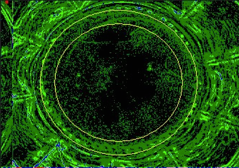
- an intermediate step is the formation of a pseudo colours (false colours) image, based on the signal grey levels corresponding to the illuminations of the pixels, one only roughly equivalent to the black and white image as seen by an Observer;
- the pseudo colours image is converted to a processed image. Here, grey levels are grouped and associated to groupings of areas. This operation allows to enhance the Signal/Noise ration, and corresponds to a smoothing of the processing. It allows to prevent false rejects on one side and undetected defects on the other. This kind of image is shown with black colour corresponding to no contrast at all, dark green colouyr to little of contrast and light green colour to superior levels of contrast. White colour is associated to the maximum levels of contrast. Contrast of groups of pixels with respect to adiacent groups of pixels. In the image on side, in evidence the base knurling marks, some of them depicted in blue and violet colours to indicate they are more contrasted than those attributed to the green or black colours;
- the figure on side shows how the Base inspection of the most advanced Linear EBI of the World looks at a square 3.0 x 3.0 mm artificial defect made of mat black colour plastic band. Say the standard material adopted to create EBIs’ test bottles. Its contour is markedly red colour in this black and white original image, where to the defect’s contour is depicted with a red colour, to highlight it. This representation superimpose the high contrast details inferred by the processed image to the black and white image shot by the CMOS- or CCD-camera.

![]() Bottles’ Base inspection adopts visible light like an instrument. Visible light 100 million times more energetic than Infrared and 100 times less energetic than, i.e. the X-rays used for the Fill Level, Case and Crate Inspections
Bottles’ Base inspection adopts visible light like an instrument. Visible light 100 million times more energetic than Infrared and 100 times less energetic than, i.e. the X-rays used for the Fill Level, Case and Crate Inspections

![]() Base Inspection’s optic is related to the distances and sizes of the bottles’ bases. These, following the kind of Electronic Inspector and its Vendor design, implies the use of multiplets of medium to short focal lengths. In the figure a LASER-cutted high quality 14-lenses multiplet by Leica®. A model implicitly limiting the false rejects (False Positives) arising by over one decade of future operation of the EBIs' most important inspection: the bottle Base. An optic of such Quality levels has a pricing ranging (1500 - 3500) $ and because of this reason you’ll never see it nor in the best and most expensive EBI existing in the World. On the opposite, low-Quality telephoto lenses, invariably valued < 500 $. This ignoring what physicists and engineers specialized in Telecommunications, High Frequency and Signals perfectly know. That to assure maximum Signal-to-Noise ratio, the electromagnetic signals have to be handled in an optimal way immediately in the antenna system. An old rule-of-thumb jokes about the fact to invest 90 % in the antenna and only 10 % in the following electronic circuit. The optics front of the vision sensor emulate some of the most important characteristics of the antennas, like the selectivity. In our special case, being interposed between the imaged object and the CMOS- or CCD-sensor, the optics are fully part of the extraction of the Information regarding defects by the electromagnetic waves
Base Inspection’s optic is related to the distances and sizes of the bottles’ bases. These, following the kind of Electronic Inspector and its Vendor design, implies the use of multiplets of medium to short focal lengths. In the figure a LASER-cutted high quality 14-lenses multiplet by Leica®. A model implicitly limiting the false rejects (False Positives) arising by over one decade of future operation of the EBIs' most important inspection: the bottle Base. An optic of such Quality levels has a pricing ranging (1500 - 3500) $ and because of this reason you’ll never see it nor in the best and most expensive EBI existing in the World. On the opposite, low-Quality telephoto lenses, invariably valued < 500 $. This ignoring what physicists and engineers specialized in Telecommunications, High Frequency and Signals perfectly know. That to assure maximum Signal-to-Noise ratio, the electromagnetic signals have to be handled in an optimal way immediately in the antenna system. An old rule-of-thumb jokes about the fact to invest 90 % in the antenna and only 10 % in the following electronic circuit. The optics front of the vision sensor emulate some of the most important characteristics of the antennas, like the selectivity. In our special case, being interposed between the imaged object and the CMOS- or CCD-sensor, the optics are fully part of the extraction of the Information regarding defects by the electromagnetic waves
To avoid


(continued)
Links to the other pages:


- EBI Classification
- Linear and Rotary EBIs
- High Frequency residual Liquid control
- IR Residual liquid control
- Base inspection, opaque defects
- Base inspection, transparent defects
- Finish inspection, crown cork
- Finish inspection, broken Thread
- External sidewall inspection, for opaque defects
- Inner sidewall inspection for opaque defects
- Mineral ring inspection
- Scuffing inspection
- Infeed checks
- Colour inspection
- Closure inspection with digital photoscanners
This website has no affiliation with, endorsement, sponsorship, or support of Heuft Systemtechnik GmbH, MingJia Packaging Inspection Tech Co., Pressco Technology Inc., miho Inspektionsysteme GmbH, Krones AG, KHS GmbH, Bbull Technology, Industrial Dynamics Co., FT System srl, Cognex Co., ICS Inex Inspection Systems, Mettler-Toledo Inc., Logics & Controls srl, Symplex Vision Systems GmbH, Teledyne Dalsa Inc., Microscan Systems Inc., Andor Technology plc, Newton Research Labs Inc., Basler AG, Datalogic SpA, Sidel AG, Matrox Electronics Systems Ltd.