Introduction
A camera system looking a transparent container and its closure can also detect the fill level in its neck. At first sight, it’d be the best and most modern system. One capable to solve in a single step all problems of closure and fill level inspection. But the reality is not so shiny and, as a matter of fact, few companies choose it. Refer to the figure below, showing a camera system observing the pattern of a bottle retro-illuminated by a rectangular array of LEDs. This basic optic configuration allows both visual closure and fill level inspections, because also the meniscus of the liquid in the container is into the camera field of view. On the opposite, the High Frequency (HF) and X-ray fill level inspections are not influenced by the neck's colour, presence of marks or logos, and only marginally influenced by the meniscus’ displacement originating by liquid acceleration. Electromagnetic waves cross all of that area, integrating the total amount of liquid by the change in:
- electric capacity (HF),
- X-photons’ counting.
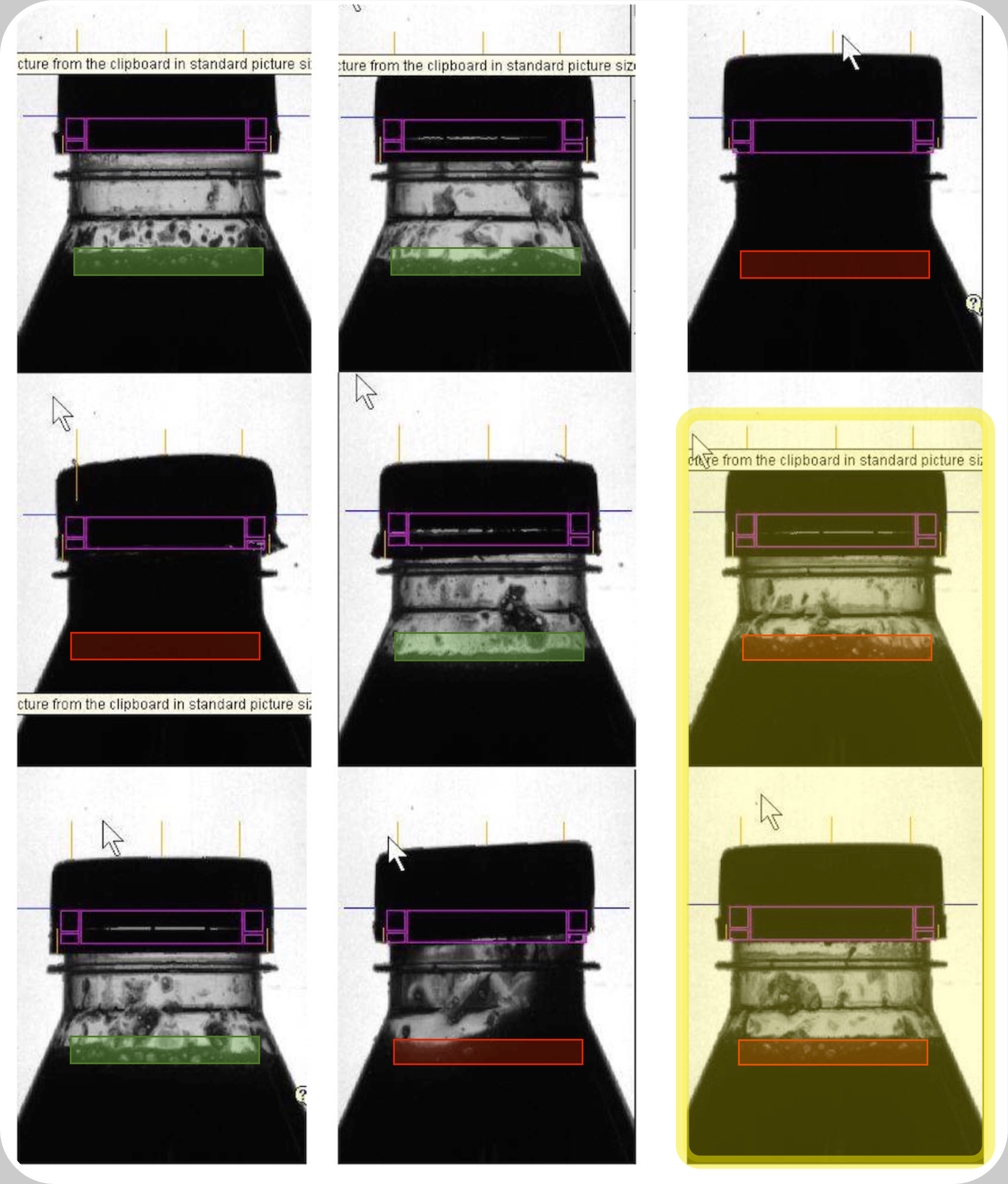
![]() In the yellow colour box False Positives (false rejects) of a Fill Level Inspection with camera. These two bottles shall be rejected also if their fill level is correct. Of them, only the lowest one in the angle at right side has at least another defect (Cap too-high). Three of the other bottles shall be all rejected (red coloured box) because leaking, with the side effect to let them all appear over-filled and because of this last reason, rejected
In the yellow colour box False Positives (false rejects) of a Fill Level Inspection with camera. These two bottles shall be rejected also if their fill level is correct. Of them, only the lowest one in the angle at right side has at least another defect (Cap too-high). Three of the other bottles shall be all rejected (red coloured box) because leaking, with the side effect to let them all appear over-filled and because of this last reason, rejected
Advantages
- Two different inspections, Fill Level and Closure, accomplished by mean of a single technology;
- a useful add-on to any other fill level inspection technology so to have redundancy, integrating the other inspection method with an additional based over a different physical principle.
Disadvantages

![]() Camera optic axe correctly oriented to the PET-container Neck Ring. Parallax error when measuring the filling level is minimised to <4º. Meniscus thickness systematic error is with this carbonated water, no added-sugar, the main cause for measurement uncertainty and deriving false rejects
Camera optic axe correctly oriented to the PET-container Neck Ring. Parallax error when measuring the filling level is minimised to <4º. Meniscus thickness systematic error is with this carbonated water, no added-sugar, the main cause for measurement uncertainty and deriving false rejects
- prone to create False Rejects. The high accuracy intrinsic in the camera technology, when checking fill level inspection results grossly reduced by other factors, adding random errors to the measurement, limiting the performances of this technology, and in between these:
- thickness of the meniscus, on the vertical dimension;
- random inclinations of the meniscus of different bottles, simply due to the fact that bottles are moving when their images are frozen;
- variations on bottle’s transparency and geometry. Vivid examples of this the nine figures above at right side;
- poor reliability. The optoelectronics know-requested to the Bottler’s Maintenance Dept. Staff is high. All optic systems based on cameras are not functioning black-boxes, like X-ray or HF: they need periodic interventions of parametric maintenance, namely on: auto-centring, delay and sensitivity parameters. If these are not performed simply because the Bottler did not received that advanced level of Training, the standard case. After a “grace-period” (1 - 3) months long inversely proportional to Line Production intensity, he’ll observe slowly growing spontaneous False Rejects. These, in the end, shall compel him to bypass the Inspector and call for Technical Assistance;
- expensive. What does not mean that it is not possible to control the filling level:
- in these kinds of bottles, whose necks and sidewalls are exempt by marks;
- filled with these beverages;
- at these linear speed and foam-related accelerations;

rather that the resulting inspection Quality results comparable with technologies (like IR- or LASER-fill level inspection) considered “poor”, where the detector itself has a commercial value <60 $ ! And, to invest (10000-20000)$ for an upgrade which can be acquired paying three times less does not appear the best way to enhance Production Quality and cut its losses.
![]() Exposure to huge False Rejects or to its opposite False Negatives (defects undetected passed to the Market) when trying to detect filling defects by mean of a camera, well visible in this PET-bottles’ necks. The bottle at left side is correctly filled like the one at right side. But, the superposed negative effects of just a little of foam and parallax error shall let the bottle at left side be rejected. On the opposite, the one at right side (visibly broken Tamper Evident Ring) is passed to the Market.
Exposure to huge False Rejects or to its opposite False Negatives (defects undetected passed to the Market) when trying to detect filling defects by mean of a camera, well visible in this PET-bottles’ necks. The bottle at left side is correctly filled like the one at right side. But, the superposed negative effects of just a little of foam and parallax error shall let the bottle at left side be rejected. On the opposite, the one at right side (visibly broken Tamper Evident Ring) is passed to the Market.
- exposed to parallax error. A camera system, like an antenna, cannot be tuned for whatever purpose or Area of Interest. As an example, the PET-bottles' Neck Rings are the typical Y-axis (vertical) reference point for the closure inspections checked by cameras. This constraints the eventual double-use of the same camera system. If the filling point and cap are not symmetric with respect to the reference point of the Neck Ring, then measurement of the cap and of the fill heights, shall be both affected by huge parallax errors. What represented at right side, evidencing the parallax errors affecting the optic measurements. Here, two PET bottles whose water beverage filling levels are correct. Camera's optic axe is in the images visibly, erroneously, oriented toward cap's top surface of a correctly capped bottle. Parallactic error is manifest yet in the Neck Ring, not seen laterally rather tilted ~6º. As a consequence, the beverage's fill level is detected under a parallax ~10º, then being just a projection of the true fill level. Now, suppose to correct camera's orientation toward the Neck Ring. Fill level measurement parallax reduces itself to ~4º. 4º of systematic errors equivalent to those of a X-Rays-, HF-, IR- or Laser-Fill Level Inspections tilted 5º because that is the angle between the entire Electronic Inspector and the Conveyor surface, say the sum of these installation errors. What before showed that if we choose the Neck Ring as a reference point, to deduce fill level in a container by mean of a camera, we cannot zero the systematic error due to the fact that all measurements happen under a parallax;
- affected by the beverage transparency. As a matter of fact (what a combination…!) the Vendors’ brochures proposing the Optic Fill Level Inspection as a modern technology superior to the pre-existing others, invariably show still waters like beverage in the bottle. Not water plus just a little of sugar, like the beverage visible here above at right side. The Cott UK beverage filled in the bottles is still water with just a little of sugar. But, that little of sugar was yet enough at a linear speed <1.0 m/s (24000 bottles-per-hour) to let water be foamy [Imagine what should have happened with the same bottle, beverage and Layout, at the 72000 bottles-per-hour guaranteed by some Vendors’ brochures !].
- influenced by container's transparency. Low transparency containers and/or those presenting marks or logos in the area of inspection, shall limit the Inspection Quality. Inspection Quality well represented in its four main parameters by the graphic below. Considering the price of the Optic Fill Level Inspection with camera, we’d expect an extremely sharp gaussian profile for the Measurement instrument (or Detector, or Receiver). One allowing to minimisation of the False Positives FP, in the graphics represented as sum of the pink- and violet-coloured areas.

![]() ROC-curve of a Fill Level inspection with camera. If the only fill level inspection existing in an Inspector, then operating with a sensitivity threshold particularly high, it’ll generate high losses (False Positives, FP). False rejects more felt with non-transparent foaming beverages, at high speed and in conveyors presenting a precedent cross-over or curve. On the opposite, if used on side of another technology (i.e., X-Rays- or HF-Fill Level) of inspection, it adds a welcome redundancy enhancing the overall Inspection Quality of the Electronic Inspector (abridged by
ROC-curve of a Fill Level inspection with camera. If the only fill level inspection existing in an Inspector, then operating with a sensitivity threshold particularly high, it’ll generate high losses (False Positives, FP). False rejects more felt with non-transparent foaming beverages, at high speed and in conveyors presenting a precedent cross-over or curve. On the opposite, if used on side of another technology (i.e., X-Rays- or HF-Fill Level) of inspection, it adds a welcome redundancy enhancing the overall Inspection Quality of the Electronic Inspector (abridged by
![]() Jutta234/CC BY-SA 3.0/2006)
Jutta234/CC BY-SA 3.0/2006)
Conclusions
The stellar performances expected by the adoption of a CMOS- or CCD-camera featuring over one million of pixels, which theoretically should have been capable to precisely let us separate two identical containers whose unique difference amounts to a filling level level <0.1 mm results, in the reality, deceptive. Reduced by the specific conditions like speed, presence of foam, precedent Conveyor’s curves preventing liquid flat upper surface, product residuals over the protective inspection panes, etc. The images above were shot on containers in movement at a linear speed <1.0 m/s in a Filler Machine outside whose production is just 24000 bottles-per-hour. Some Vendors are advertising their systems presenting them textually as “ultra-performant” until a production speed of 72000 bottles-per-hour. But, in the brochures they are not citing that:
- the beverages used during testing, before to compile any Technical Guarantee, showed a meniscus featuring particularly pronounced grey levels, making it extremely easy to univoquely detect a level;
- no foam at all was present, just still and sparkling waters.
- several other limits and conditions which do not affect all other Fill Level technologies.
Performances and respect of Contracts
The situations hinted before, have the strictest relation with the illusory guarantees of the High Frequency Fill Level inspections. Those sold to detect and reject an under- or over-filling of 2.0 mm with a hit ratio >99.9 % and an associated false rejects ratio <0.01 %. Later discovering that the environmental conditions (ambient humidity and temperature), condition negatively all of the High Frequency Fill level Inspections in the World, whatever their Vendor. Condition reducing the inspection performances to >5.0 mm under-filled filling detected with a hit ratio >99.9 % and an associated false rejects ratio <0.01 %.
[By a couple of Commercial Directors, we know that there are also Vendors who cutted in their brochures 10 times the defects’ hit ratio to let it look 99.99 %, 10 times better than a Competitor's 99.9 %…]
Then, you change the position of that identical High Frequency Fill Level inspection, setting it directly in a thermostatic and humidity-controlled clean room. A typical case of the Aseptic filling. And you discover only minimal ameliorations, far from what is written in the Technical Guarantees.
Now, Vendor says that the problem arise directly in the fluctuations of the beverage’s temperature, what is true. And you invest to upgrade the fill level inspection system, adding a thermal linearisation on the base of the beverage's temperature, measured directly in the Filler tank. ...and, one more time, you discover that there is no way to detect and reject a 2.0 mm under- or over-filling with a hit ratio 99.9 % and an associated false rejects ratio < 0.01 %.
Now, you are just a phone call far from hearing what no one shall never write you in a Technical Guarantee or in an e-mail (also when filled with Disclaimers’ statements): that Technical Guarantee is not really a Technical Guarantee. It is truly fulfilled only if your bottle is (comically) standing still stopped over the Conveyor, under the High Frequency Fill Level inspection bridge…..!
That 5 % of the Bottling Companies
Finally, if your Company is one in that 5 % of those capable to let their contractual rights be defended, you know you have full right to ask and obtain alternatively:
- an indemnisation, and remain with the present system,
- replacement of that inspection with another of that same Vendor (offering superior performances), and the commissioning of all formats included;
- replacement of just that inspection with one from another Vendor, paid completely by the Vendor, installation and commissioning of all formats included, what is feasible and better choice when the Inspector you acquired has digital inputs available to process, count and reject the named External Inputs. “External Inputs” corresponding to optocoupled, potential-free digital signals (on-off, 0 or 5 volt)
- replacement of that Electronic Inspector with one from another Vendor, paid completely by the Vendor, installation and commissioning of all formats included,
or, pass that Contract and a list of evidences for all what happened to your Legal Dept. who shall treat the case under the rules of the Civil Law enforced in the country agreed in the Contract imagining unexpected developements like these in mind.
Links to other pages with similar topics:


